Milling equipment must be moved along the surface of the product, which is firmly fixed and stationary. To ensure comfortable work with small analogues, experts recommend making a table for the router with your own hands. On this design, the machine can be fixed permanently, which allows you to move the workpiece, quickly removing the overhangs and processing ends.
")
A special table for the router is necessary for the convenience of working with this tool.
Basic work
Experts identify the following types of such structures:
- stationary;
- portable;
- aggregate .
The fixed structure can be used for any operations if the installation is dismantled. Portable table top for a milling cutter is suitable if the need for such activity occurs infrequently. The convenience of the proposed design is that it can be easily moved by hand. Before deciding how to make a table for a milling cutter, it is necessary to become familiar with the constituent elements of the product:
")
Table dimensions for a milling cutter.
- Bed.
- Tabletop.
- Mounting plate.
- Clamps and stops.
Most quickly and without unnecessary effort, you can construct a table for a milling cutter, using the finished product and adding it with fasteners, clamps and stops. The bed includes the frame and the surface of the table top to perform a manual router. It is made of wood, MDF, chipboard or metal profiles. Experts recommend the use of metal profiles. Butt joints are preferably twisted using bolts. Such a solution will give the design high strength.
The size of the bed can be any and depends on the parameters of the workpiece. It is recommended to deepen the lower part of the frame in relation to the overhang by about 20 cm. One of the most important parameters of such structures is their height. Experts recommend making a stand with a height of 1 m for standing. If necessary, make a table with adjustable supports.
Production process
")
Table drawing for the router.
The cover is made of chipboard 25-40 mm thick. Solid and smooth material contributes to the smooth sliding of the workpiece and well dampens vibration. You can make the cover of the product for a manual mill of phenol plastic. This material is durable, durable and easy to process.
The most reliable and durable table covers for the router are made of aluminum. The advantages of this material include:
- lightness;
- corrosion resistance;
- durability.
Aluminum should be clad to avoid metal marks on the workpieces. The next step involves arranging the holes for the mounting plate. To do this, you need to cut the plate (taking into account the parameters of the future design). The resulting product is placed in the center of the lid, making indent from the front edge of 125 mm. Then trace its contour. Make the markup and put a cutout line on the inner edge of the contour.
")
Table design for a milling machine.
The hole is drilled using a jigsaw. The plate is mounted inside the contour with double-sided tape. Then fix the guide rails with a clamp, insert the strip of cardboard. Similar inserts and plate are removed. The next stage involves the installation of a copy milling cutter with an upper bearing in the collet. Milling depth must be 3 mm.
To level the product, you will need nuts. It is recommended to make a recess and drill holes in its corners with a depth of 6 mm and a diameter of 11 mm. Nuts should not protrude. In the center of the holes intended for nuts, additionally make through holes for the screws.
Making the stop and the comb
To make an even stop, you will need to otgugovat edges well. Pre-cut the stop and its base (making allowances of 12 mm in width and 25 mm in length). Then the longitudinal analogue is realized. To the length of the finished cover add 1 mm. Emphasis sawn. With the help of jigsaw make a cutout in 38x38 mm. The stop is glued to the base and fixed with clamps. The next stage involves the production of two blanks for the end plate (parameters 19x120x190 mm). The resulting parts are combined into a block with scotch tape. On the top of the workpiece make the markup. The cut is made, the edge is ground. In the product make a hole with a diameter of 6 mm.
")
Drawing of the cover for the milling table.
The end plates are separated and glued to the stop. It is necessary to align their edges, focusing on the front side of the last element. Gluing is fixed with clamps. Through-holes are made in the plates into which the screws are screwed. Using a slotted disc in the support, a groove is cut out.To install the nozzle, you need to cut kerchiefs. The last elements are fixed to the stop with clamps. If the glue is dry, then it is necessary to find the center of the mounting holes for the fasteners.
To make a clamping comb, you need a straight-layer maple board 19 mm thick. The billet should have dimensions of 51x457 mm. Angular focus on the machine make bevels, observing an angle of 30 °. Across the workpiece spend oblique lines, making indent from the ends of 67 mm. In the machine set the disk thickness of 3 mm. It must be raised to a height of 50 mm above the table. The emphasis is moved away from the disk at a distance of 2 mm. Board taken back. The workpiece is rotated 180 °. Then move the longitudinal support to 5 mm. At both ends make new cuts. A similar operation is repeated in increments of 45 mm.
")
Drawing of the cover for the milling table.
After installing the longitudinal stop, the saw blade is lowered to a height of 25 mm. The edge of the workpiece is sawn to the desired width. In the clips make holes with a diameter of 7 mm (for mounting the suspension). Parallel lines mark the edges of the slit holes. They can be cut out with an electric jigsaw. Clamping dies are ground with sandpaper.
7 mm holes are made in the center of the locking elements. The blocks are ground and mounted to the edges with clamping dies. This technology prevents the first elements from turning when feeding blanks.
To adjust the pressure of the pressure comb, the length of the first plate should be 3 mm shorter than the other analogues.
In the adjustment process, the shortened part is pressed against the workpiece. The comb is attached to the main structure with a screw.
The base of the tabletop
The screeds and legs of a given length are cut with an allowance of 25 mm in width. The saw blade can be tilted 12 °, sawing off the bevels at the edges of the legs and the edges of the screeds. Experts recommend pre-cut the bar for the power cord.
The ties are glued to the legs and secured with clamps. Through the first elements the guide holes are drilled, screws are screwed into them. Clamps are removed. The strip for the power cord is glued to the screed and secured with clamps. The assembled legs need to be sanded using 220 grit sandpaper. An inverted lid is placed on a workbench, sticking the assembled legs to it. The blank for clamping dies can be cut from a maple straight-layer board, which is 19 mm thick.
The next step involves assembling the table. To do this, you need to twist the frame to which the table top will be attached. At the corners of the surface should be 2 fasteners. Along the edges, the last elements are screwed in increments of 50 cm.
The nest into which the mounting plate will be inserted must have rounded corners. After installation, it is necessary to make a hole in it that will correspond to the shape of the sole of the milling machine. By combining all the details, you can proceed to trial work to assess the quality of the assembly and, if necessary, correct it.
Didn't find the answer in the article? More information on the topic:
-
")
How to make a wooden floor on the ground?
Wooden floor on the ground: the device of the coating, the required materials and tools. Technical features of the work stages. The process of mounting your own hands.
Search
Related Articles
Do-it-yourself folding chair: detailing, assembly process
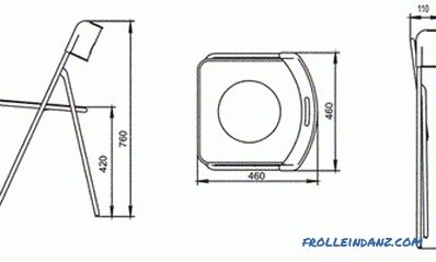
The chair acts as one of the most necessary pieces of furniture, be it a home space or a country plot. You can buy such furniture in the store, and you can make a chair with your own hands. The in...
drawing and assembly of furniture (photo)
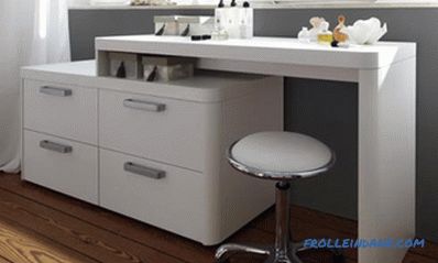
You can not do without an elegant and comfortable dressing table in the bedroom. Otherwise, where should the hostess fold cosmetics and necessary trifles? And a large mirror is not a luxury, but a...
Stool do-it-yourself from chipboard: several stages of work
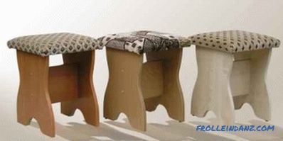
In any home there is always some kind of furniture. In the kitchen, most often used table, all sorts of wall and floor cabinets, simple stools. These seats have a fairly simple design, they are not...
Rating dishwashers TOP 10 best 2019

We present to your attention the rating of dishwashers, based on consumer reviews. When selecting goods, we rely not only on the technical characteristics specified by manufacturers, but also take i...
How to make a fence from the fence

Metal, wooden or even plastic narrow strips from which a fence can be assembled are commonly called a picket fence. However, despite this "generalized" name, the fences made from them can end up bei...