Calculation of wooden floor beams is in demand both for residential attic floors, second floors, and for unexploited attics. Low fire safety, resistance to fungus infestation of wooden structures is compensated by affordable price, low weight, manual installation. When starting the section calculation, it is necessary to take into account several parameters recommended by specialists:
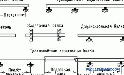
Species of floor beams.
- resting on a wall from 12 cm;
- a rectangular cross section with a ratio of 7/5 (height is always greater than width);
- span 4 - 2, 5 m (placement on the short side of the rectangle);
- permissible deflection is 1/200 (2 cm at the recommended length).
For convenience of calculation, a static load is applied with a margin equal to 200 kg or 400 kg per unit area for attics and exploited premises, respectively. This method eliminates lengthy calculations of operational loads - people, furniture, household utensils. Most often, the floors of the upper level are based on logs, therefore, concentrated loads are actually present. In practice, the amount of lag exceeds 5-7, so the load is taken evenly distributed.
Calculations are reduced to the definition of a rational section of lumber, providing 20-30% strength stock with a minimum construction budget. With a large step of beams, laying the plank floor without lag, the minimum possible section of the floorboard is additionally calculated.
Example of the calculation of a wooden beam

Figure 1. Table with the characteristics of the design resistance of materials of different humidity.
The calculation of the overlap begins with determining the bending moment for the operating conditions. The formula applies:
M = N x L 2 / 8, where L is the span length, N is the load per unit area.
A four-meter overlap over a span of 4 m for the floor / attic in operation in this case is experiencing a bending moment when the beam spans 1 m:
M = 400 kg / m 2 x 4 2 m / 8 = 800 kgm (to bring into a single system of units 80,000 kgcm)
The SNiP standards contain tables with the characteristics of the design resistance of materials of different humidity. Fig. 1.
The parameter is denoted by the letter R, is for conifers, most often used in the supporting structures of cottages due to its low cost, 14 MPa. When converting to more convenient units, this value will be 142.7 kg / cm 2 . Providing a margin of safety, the figure is rounded down to 140 units for future use. Thus, each overlap element will require a moment of resistance:
W = M / R.
In the example with the specified conditions, the overlap should have the value:
W = 80 000/140 = 571 cm 3
For beams, the bar with rectangular section. The moment of resistance of elements of this form is determined by the formula:
W = a x h 2 / 6.

Figure 2. Table for calculating the resistance of various tree species.
In this formula, two parameters are initially unknown - height h, width a. Substituting one value (width) into it, the second side of the section (height), which the overlap beam has, is easily calculated:
- we find 6W / a;
- we take the root from this value.
In our case, h = 18.5 cm with a width of 10 cm. The nearest standard bar section of 20 x 10 cm fully meets the requirements.
Dependence on the spacing of the wooden beams
If the distance between the axes of single-span wooden beams is changed in any direction, the dimensions of the section of the beam and the boards used as floor covering will change. Therefore, it is recommended to perform several calculations with different parameters to achieve a minimum construction budget.
In our example, a wooden beam turned out to be 20/10 cm, the amount of sawn timber for the whole room 6 x 4 m will be 7 pcs. (0.56 cube).
The calculation of wooden beams for the same conditions with a step of 0.75 m will reduce the bending moment to 60,000 kgcm, the moment of resistance to 420 cm 3 , the height of the beam to 15.9 cm. In this In this case, you will need 9 beams 17.5 x 10 cm (0.63 cubic meters of timber).
The calculation of wooden beams with a pitch of 0.5 m will reduce these characteristics to 40,000 kg / cm, 280 cm 3 , and 12.9 cm, respectively. The number of beams will increase to 13, lumber to 0.78 cubes.
In the first case, the 50th or 40th plank will be required for the floor; in the latter case, an "inch" is sufficient, which will significantly reduce the construction budget.
Specificity of calculations of wooden floors
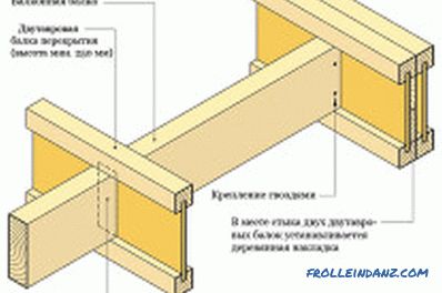
Figure 3. Layout of installation of floor beams.
In the regulations of the SNiP, there are other tables needed in the calculations for tree species differing in characteristics from pine, spruce (Fig. 2).In addition, there are construction resource coefficients:
- to ensure the age-long reliability of k = 0.8;
- operation within 50-90 years is ensured with k = 0.9;
- if 50-year reliability is sufficient, apply k = 1.
The calculated resistance of the beam is multiplied by this factor, the minimum allowable width / height of the sawn timber section is increased.
The calculations performed are not enough to validate the selected beam. It is necessary to calculate the deflection of the structure, compare it with the permissible possible. The articulated beams are adopted for operation, the formula is as follows:
F = 5NL 4 / IE, where E is the modulus of elasticity of lumber, I is the moment of inertia.
The first characteristic of a beam depends on the material, the same for all wood species - 100,000 kg / cm 2 . However, depending on the humidity, the value varies from 110,000 to 70,000 kg / cm 2 .
The moment of inertia is equal to:
I = a x h 3 / 12.
What for the conditions considered in the example will be:
I = 10 x 20 3 / 12 = 6 666 cm 4 .
After which the deflection of the beams will be:
F = 5 x 400 kg x 4 4 m / 384 x 100 000 = 2 cm.
Norms of SNiP regulate the deflection of wooden floor beams within 1.6 cm. Therefore, the condition is not met, the following value of sawn timber is taken.
Practice shows that with the step of beams of 1 m, 4 cm of the floorboard is enough; if you reduce the step to 0.75 m, you can do with a 35 mm board.
"Dimple" (25 mm plank) is usually used in unoperated attics with a beam spacing of 0.5 m. In other cases, it is recommended to make calculations similar to those considered for flooring boards. In this case, the span length is reduced to the distance from the edge of the beam to the edge of the neighboring element.
When using multilayer plywood, it is recommended to use 14 mm sheets on beams with a pitch of 0.75 m, 18 mm sheets at a pitch of 1 m. The use of chipboard as a subfloor is not recommended, it is better to replace the material with OSB, which has a large resource. Fig. 3.
If lags are used between the flooring and the floor beams, the calculation of sawn timber is identical to that considered in the example. In practice, a section of 10 x 7 cm is sufficient.
Normally, strength analysis is used under standard operating conditions:
- cladding in the form of laminate, parquet, linoleum;
- no plaster.
If you plan to plaster the ceiling, tile the wooden floor with tiles, the calculation of the deflection is much more important. In this case, instead of the recommended SNiP permissible value 1/20 of the span length, the value 1/350 is used. Otherwise, the tile will peel off with a short-term increase in operating loads. In this case, the draft floor is made of hard wood-containing boards or multi-layer plywood, and not of boards. Under difficult operating conditions, wooden beams are either shifted to 0.4-0.5 m, or are replaced by rolled metal.
Didn't find the answer in the article? More information on the topic:
-
How to calculate the log volume correctly?
How to calculate the volume of a log correctly, which calculation methods allow you to accurately estimate the volume of roundwood? Calculation of the volume of occupied space, individual logs, tables.
-
How to determine how much a bar is in a cube?
Recommendations on how to correctly calculate how much timber in a cube. Calculation of the required amount of timber. The amount of material in one cube. Calculate total losses.
-
Features of the calculation of wood floors
Step by Step instructions on how to make a calculation of the wooden floor. Determination of the main parameters: the length of the wooden beams, the calculation of the load on the overlap, etc.
