In modern individual construction, wooden beams are used in almost every project. Finding a building that does not use hardwood floors is almost impossible. Wooden beams are used both for the device of floors, and as bearing elements, as supports for interfloor and attic floors.
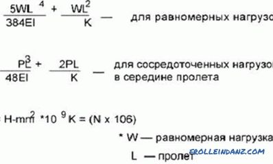
The formula for calculating the deflection of a beam.
It is known that wooden beams, like any other, can sag under the influence of various loads. This value - deflection arrow - depends on the material, the nature of the load and the geometric characteristics of the structure. A small deflection is quite acceptable. When we walk, for example, on wooden flooring, we feel the floor slightly springy, but if such deformations are minor, then it doesn’t bother us much.
How far deflection can be allowed is determined by two factors:
- The deflection should not exceed the calculated allowable values.
- The deflection should not interfere with the operation of the building.
To find out how much wooden elements will be deformed in a particular case, you need to make calculations for strength and stiffness. Detailed and detailed calculations of this kind are the work of civil engineers, however, having the skill of mathematical calculations and knowing several formulas from the course of resistance of materials, it is quite possible to independently calculate a wooden beam.
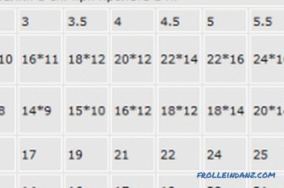
Auxiliary table for calculating the number of beams.
Any construction must be solid. That is why the floor beams are checked first of all for strength, so that the structure can withstand all the necessary loads without collapsing. In addition to strength, the structure must have rigidity and stability. The amount of deflection is a calculation element for stiffness.
Strength and rigidity are inextricably linked. First, make calculations for strength, and then, using the results, you can make a calculation of the deflection.
In order to properly design your own country house, it is not necessary to know the full course of material resistance. But to go into too detailed calculations is not worth it, as well as calculate the various designs.
In order not to be mistaken, it is better to use the enlarged calculations, using simple schemes, and calculating the load on the bearing elements, always make a small margin in a big way.
Algorithm for calculating deflection
Consider a simplified calculation scheme, omitting some special terms and formulas for calculating the two main load cases taken in construction.
It is necessary to perform the following actions:
- Create a design diagram and determine the geometric characteristics of the beam.
- Determine the maximum load on this carrier.
- If necessary, check the timber for bending strength.
- Calculate the maximum deflection.
The design scheme of the beam and the moment of inertia
The design scheme is quite simple to make. You need to know the size and shape of the cross section of the structural element, the method of support, as well as the span, that is, the distance between the supports. For example, if you lay the supporting beams of the ceiling on the bearing walls of the house, and the distance between the walls is 4 m, the span will be l = 4 m.
The wooden beams are calculated as freely supported. If it is an overlap beam, then a circuit with a uniformly distributed load q is taken. If it is necessary to determine the bend from the concentrated load (for example, from a small stove lined directly on the floor), a circuit with a concentrated load F equal to the weight that will press on the structure is taken.
To determine the magnitude of the deflection f, a geometrical characteristic is required, such as the moment of inertia of the section J.
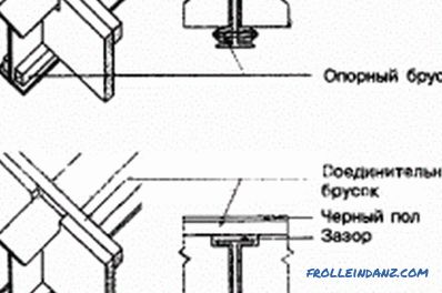
Installation scheme of wooden beams overlaps.
For a rectangular section, the moment of inertia is calculated by the formula:
J = b * h ^ 3/12, where:
b is the section width;
h is the height of the beam section.
For example, for a section of 15x20 cm in size, the moment of inertia will be:
J = 15 * 20 ^ 3/12 = 10 000 cm ^ 4 = 0.0001 m ^ 4.
Here it is necessary to pay attention to the fact that the moment of inertia of a rectangular cross section depends on how it is oriented in space. If the cant is put on the supports with a wide side, then the moment of inertia will be much less, and the deflection will be more. Everyone can feel this effect in practice. Everyone knows that the board, laid in the usual way, bends much more than the same board laid on the edge. This property is very well reflected in the formula itself for calculating the moment of inertia.
Determining the maximum load
To determine the maximum load on the beam, you need to add all its components: the weight of the beam itself, the weight of the floor, the weight of the environment with the people there, the weight of the partitions. All this needs to be done in terms of 1 st. m beams.Thus, the load q will consist of the following indicators:
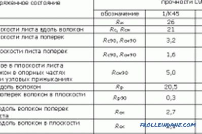
Calculation for crushing of the support sections of the beam.
- weight 1 st. m beams;
- weight of 1 square. m overlap;
- temporary load on the overlap;
- load from partitions per 1 square. m overlap.
In addition, we must take into account the coefficient k, equal to the distance between the beams, measured in meters.
To simplify the calculations, you can take an average overlap weight of 60 kg / m², a standard temporary overlap load of 250 kg / m², the load from partitions according to the same standards, 75 kg / m², the weight of a wooden beam can be calculate, knowing the volume and density of wood. For a section of 0.15 x 0.2 m, this weight will be equal to 18 kg / bar. m. If the distance between the bars of the overlap is 600 mm, then the coefficient k is equal to 0.6.
We count: q = (60 + 250 + 75) * 0.6 + 18 = 249 kg / m.
We now turn to the calculation of the maximum deflection.
Calculations of the maximum deflection
For the case under consideration with a uniformly distributed load, the maximum deflection is calculated by the formula:
f = -5 * q * l ^ 4/384 * E * J .
In this formula, the value of E is the modulus of elasticity of the material. For wood E = 100,000 kgf / m².
Substituting the values obtained earlier, we find that the maximum deflection of a wooden beam with a section of 0.15x0.2 m and a length of 4 m will be equal to 0.83 cm.
If we accept the calculated circuit with a concentrated load, the formula for calculating the deflection will be different:
f = -F * l ^ 3/48 * E * J, where:
F is the pressure force on the beam, for example, the weight of the furnace or other heavy equipment.
The modulus of elasticity E for different types of wood is different, this characteristic depends not only on the type of wood, but also on the type of timber - solid beams, glued laminated timber or a rounded log have different elastic moduli.
Similar calculations can be made for various purposes. If you just need to find out within what limits the deformations of the structural elements will be, after defining the deflection arrow, the matter can be considered completed. But if you are interested in how the results obtained correspond to the construction standards, then it is necessary to compare the results obtained with the figures given in the relevant regulatory documents.
Didn't find the answer in the article? More information on the topic:
-
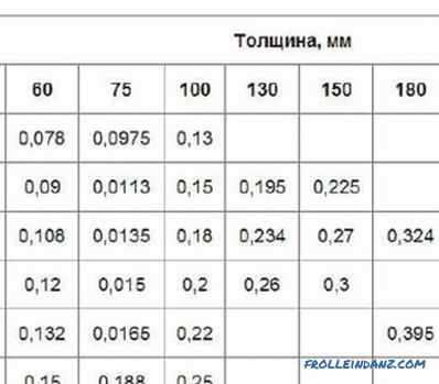
How to calculate the cost of timber per house?
Information that gives an idea of how to calculate the beam for the construction of a log house. The parameters of the lumber and log walls, which are required when calculating the flow.
-
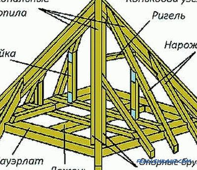
Perform the calculation of roof rafters
The calculation of the rafters includes the determination of the pitch of the racks, the section of the timber. The configuration of the roof, the scheme of supporting the legs on the mauerlat, the joints in the ridge, the use of crossbars, racks are taken into account.
-
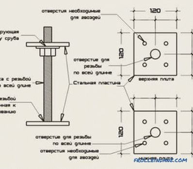
What influences the shrinkage of the log house?
Shrinkage of the log: factors that affect it. Preventive measures and work during the shrinkage process. Tools and materials needed for work.
