The calculation of the truss system acts as the main design process of the building, this allows you to determine the parameters of the carrier system.
")
The structure of the gable roof of the house.
Features of the calculation of the truss system
Before starting to calculate the system of rafters, it is necessary to analyze how intense are the loads that act on the roof surface during the entire period of the year.
")
Figure 1. Calculation of the load on the rafters.
We can single out factors that, depending on the natural conditions, are divided into:
- constant effects;
- variable effects;
- special loads.
The first category is the load that continuously acts on the truss system: the weight of the roof, the waterproofing layer, the sheathing system, heat and vapor insulation, as well as other components related to the gable or mansard roof system. Thus, constant loads have a continuous effect and have a fixed weight. Among the variable loads are climatic factors according to the type of precipitation, snow, wind flow, etc. Special factors are those caused by climatic influence with a higher degree of intensity. This parameter should be taken into account in territorial areas with the possibility of seismic activity or in areas where strong hurricanes and storms can occur.
Calculation of a constant load
")
Scheme of construction of a truss system of a gable roof.
In fig. 1 you can see the calculation of the load on the system rafters. In order to correctly determine the length of the rafter and the data to be oriented, it is first necessary to calculate the mass of the roofing “pie”. In order to get the final value, the weight of 1 m 2 of each layer should be calculated. As a rule, the roof consists of the following elements. Crate, which is equipped with boards with a small thickness (2.5 cm). Weight 1 m 2 crates equal to 15 kg. The system also contains the following components: heat insulator, waterproofing, finishing coating. After the weight of each component has been determined, depending on the material used, 10% should be added to the result, this will slightly increase the strength of the truss.
Professional developers recommend choosing materials for arranging the roofing “pie” so that the load level eventually does not turn out to be more than 50 kg per 1 m 2 . At the next stage, you can begin to determine the snow load.
Calculation of snow load
")
Connection and attachment scheme for rafter legs and power plate.
In order to calculate the snow load, you should use the formula in which you want to substitute the SNiP coefficients. The formula has the following form:
F = P * k, where F is the total snow load, P is the mass of precipitation per 1 m 2 , while k is the correction factor.
In the SNiP, you can also find a correction factor, the variation of which occurs depending on the level of the slope of the roof. If there is a slope that exceeds 60 °, the coefficient should not be used; when the slope is in the range of 25-69 °, a correction factor should be applied, which is equivalent to 0.7. Roofs that have even smaller slopes of slopes require the use of an adjustment equal to 1.
Snow along the attic or other roof of the sloping structure is unevenly distributed, the largest clusters are formed in the fracture areas.
The rafter legs at such points should be mounted with the smallest pitch, the installation of paired components is the best option. Among other things, when arranging the layers of the roofing “pie” in particularly difficult areas, double waterproofing should be used, as well as a continuous type of crate.
Calculation of wind load
")
Figure 2. Table of calculation of the rafter foot.
If the house has a slight angle of inclination of the roof, then there is a probability that the roof system will be damaged and torn down, which will be affected by aerodynamic load. But a more significant bias can cause the roof to be subjected to high wind pressure. To determine the wind load on the roof should use the formula with correction factors. It has the following form: V = R * k, in it V is the level of wind load, R is the level of a specific region, the designation k is represented by a correction factor.
The region indicator is a tabular value prescribed in the SNiP, and the correction factor must be chosen in accordance with the height of the building and the area on which the building is installed.The coefficient varies as follows:
- The indicator for buildings in open areas and with a height of 20 m is equivalent to 1.25;
- if there are obstacles in the form of tall houses or landing factor will be equal to 0.85;
- if the calculation is carried out for a building with a height of 10 m, amendment 1.0 and 0.65 should be used;
- indicators 0.75 and 0, 85 are used to determine the load on low houses up to 5 m, depending on the construction site.
Calculation of the system of rafters
")
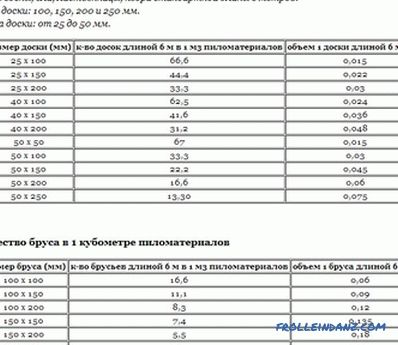
Figure 3. Lumber size chart.
It is impossible to correctly calculate the system of rafters, if the load indicators, the spacing between the spans, the distance between the crate are not taken into account. In the process of calculating the structure, it is permissible to use a table of standards. It is necessary to select the cross section of the rafter legs, taking into account factors including:
- the dimensions of the rafter foot;
- the distance between the rafters;
- the calculated load figures.
In order to select the most appropriate value for cross sections of a rafter foot, use the table in fig. 2. Recommended parameters may vary depending on the area in which the house is built. The easiest way to calculate a truss structure is to determine the dimensions of a rafter foot. In order to get the right value, you need to apply the Pythagorean theorem, in this case, the difference in height will act as the legs, to determine the value of the walls of the building and its width, but the hypotenuse will become a truss, its length will be determined initially.
Due to the fact that the system contains rafter legs, the calculation must be made, determining the load on each leg separately. In order to find the distributed load on the meter foot, you need to use the formula: Qr = АхQ, in it Qr is the distributed load in kg / m; the letter A is represented by the step between the rafters, in meters; Q - total load per 1 m ² of the roof, in kg / m². In the truss foot, you need to determine the working area of the greatest length Lmax. Further, it is necessary to determine the smallest section of leg material. In the process of selecting the material for the rafters, you should use a table of sizes of lumber (Fig. 3).
")
Figure 4. Example of calculation of truss systems.
The width of the section can be set arbitrarily according to standard dimensions, and the height of the section can be determined by the formula: H ≥ 8.6. Lmax. sqrt (Qr / (B. Rizg)), with the slope of the roof α. 30 °, H ≥ 9.5. Lmax. sqrt (Qr / (B. Rizg)), with a slope α. thirty.
H is the section height in centimeters, Lmax is represented by the working section of the truss foot of the greatest length in meters, Qr is the distributed load per 1 meter of foot, in kg / m, B is the section width in centimeters, Rizg - material resistance to bending, in kg / cm², sqrt is the square root.
Now you can analyze whether the deflection index meets the standard. The normalized deflection under load for roof elements should not be greater than L / 200, where L is the length of the work area, presented in centimeters. This condition is true if the following inequality is true: 3.125. Qr. (Lmax) ³ / (B. H³) ≤ 1, here Qr is the distributed load per 1 m. Of foot, expressed in kg / m; Lmax - the working area of the foot of the greatest length in meters; B is the width of the section, expressed in centimeters; H - section height in centimeters. In case of non-compliance with the inequality it is necessary to increase B or H.
In fig. 4 you can see an example of the calculation of the truss system. If you do not have skills in this area, the calculation can be made using special programs.
Didn't find the answer in the article? More information on the topic:
Search
Related Articles
laminate or floorboard, comparing the characteristics of two coatings

When people start redecorating in the house, which involves changing the flooring, many do not know what to choose: laminate flooring or floorboard? Of course, much preferable flooring. She is very...
Calculation of lumber: table cubic
In any work with wood, it is necessary to be able to calculate lumber, as well as draw up any tables. This lesson requires some skill and a number of small skills, but to do something wrong will be...
Aging wood: technology to create a decorative effect
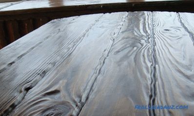
The aging of wood occurs over a long time as a result of exposure to moisture, temperature changes, sunlight and other natural factors. To imitate the type of an aged wood product, it is machined a...
Facing brick types and colors of photo textures and shapes
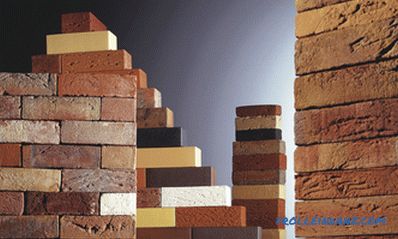
The facing brick is outwardly more attractive than the ordinary one - after all, it is an element of the wall decoration and should not “hit the face with dirt”. It is used not only for cladding, bu...
Expanded clay density - bulk, true and specific
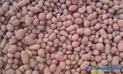
At the moment, expanded clay is the most popular eco-friendly insulation. This building material is distinguished by its small mass and cellular structure. The density of expanded clay, as a rule, h...